Headlight Bonger Project
DESCRIPTION
Automobile Aftermarket Accessory This device is referred to as the “Headlight Bonger” or simply the “Bonger.” The Bonger produces a warning sound when a motorists shuts off their car’s engine but has left the headlights on. The hobbyist project was completed in 1982 and was produced in small quantities.
BACKGROUND AND DEVELOPMENT
The part of the Bonger that makes the alarm noise is a Piezo Ceramic Audio Transducer. The transducer I choose is an “AT-23” from Projects Unlimited Inc. and I purchased them from D. Dolan Sales Co. in Milwaukee Wisconsin. This was done in 1982 and I haven’t checked on the supplier since then. These devices aren’t unusual however. I modeled the electronics for the Bonger starting with the suggested circuits in the device manufacturer’s data sheet. The data sheet for the similar but a bit more expensive AT-21 transducer and the AT-23 transducers (which was used) are shown in the figures below.
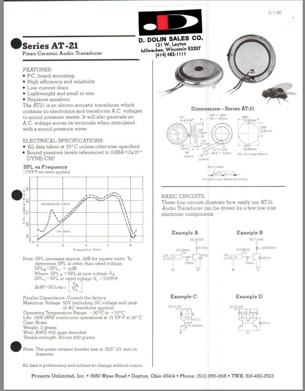
Figure 1 - AT-21 Alarm Transducer. (Similar to the AT-23)
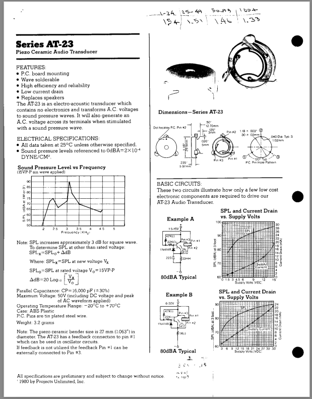
Figure 2 - AT-23 Alarm Transducer (Used in the Bonger)
I designed and debugged the original circuit for the Bonger on a special “Pin Block” prototyping board. The initial build of Bongers were done on small single-sided printed circuit boards (PCB), 1.5 inch X 1.5 inch. The parts were a bit crowded, so much so that the AT-23 was attached to the opposite side of the PCB from the rest of the components. See the photo below.
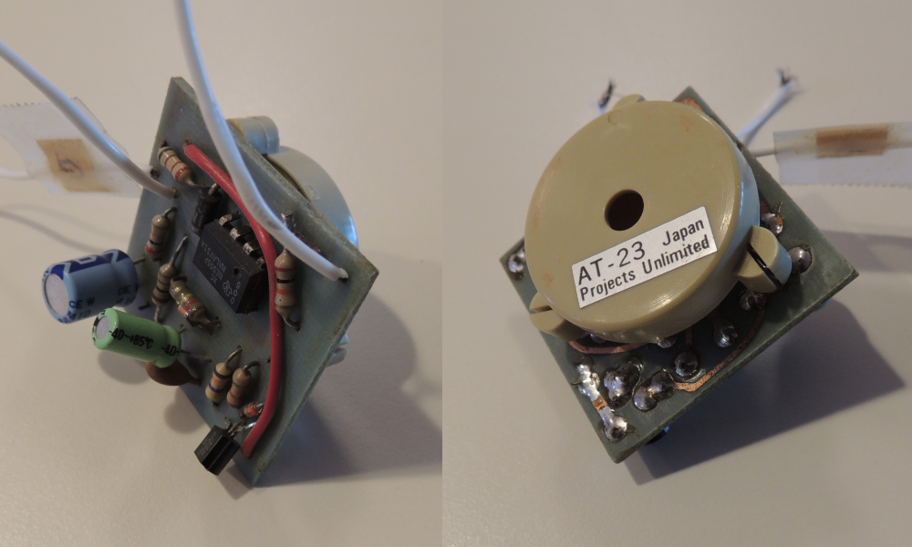
Figure 3 - First Bonger Assembly - 1.5” X 1.5” PCB
I ended up actually building only a few of these 1st-run-Bongers and used my car to prove out the concept.
I went ahead and purchased an additional 25 larger (and therefore less crowded) PCB for a 2nd set of Bongers. A finished example of one of this next generation of Bongers is shown in the next three figures.
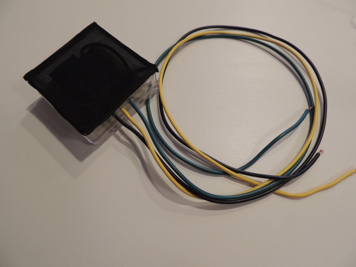
Figure 4 - Headlight Bonger Top View
This view shows the finished headlight longer. The circuit board was glued into a 2.5” X 2.5” X 1” plastic box. The three wires were intended to be connected to the Plus 12 volts, Ground and a wire that came on with the headlights. A friend of mine provided the thin black fabric covering over the top of the open plastic box. This prevented the cover of the box from muting the sound of the AT-23.
The bottom view and edgewise view of the Bonger are shown in the figures below.
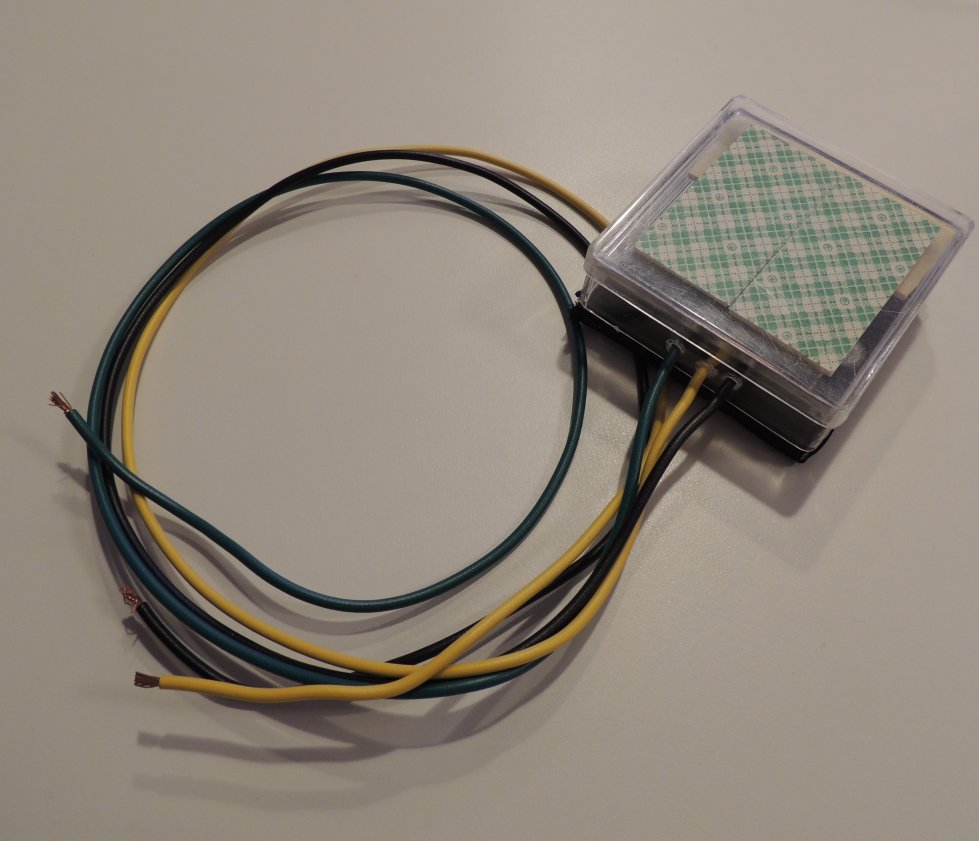
Figure 5 - Headlight Bonger Bottom View
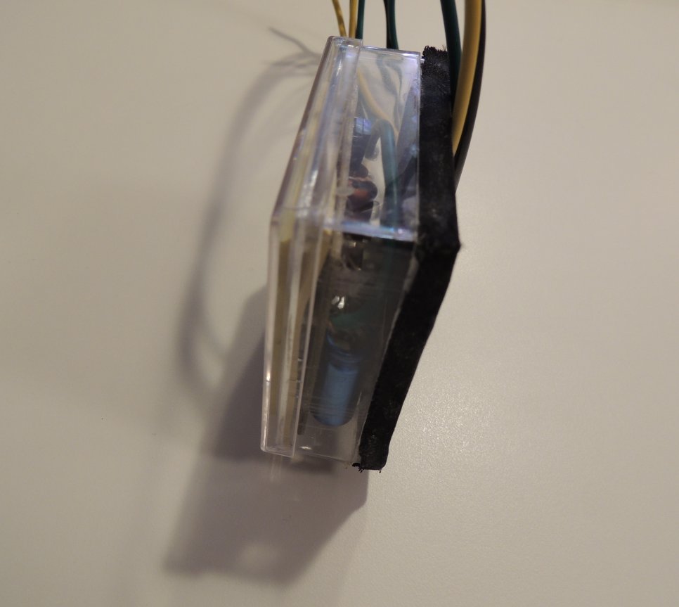
Figure 6 - Headlight Bonger Edge View
The bottom view shows pad of double stick foam that was attached to the bottom of the plastic box. You can see it through the box’s cover which was clamped onto the bottom to protect the foam pad during shipping. This lid is basically a “throw away” item as it had no function once the Bonger is installed.
Three so-called “Scotch Locks” were included with the Bonger. Scotch Locks were commonly used for modifying wiring in automobiles. I generated a brief set of installation instructions for the Bonger. The installation instructions are shown in the figure below.
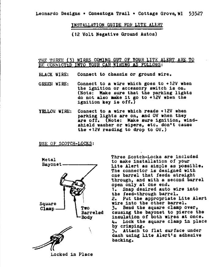
Figure 7 - Bonger Installation Instructions.
SCHEMATIC AND PARTS LIST
The schematic diagram and parts list are shown below.
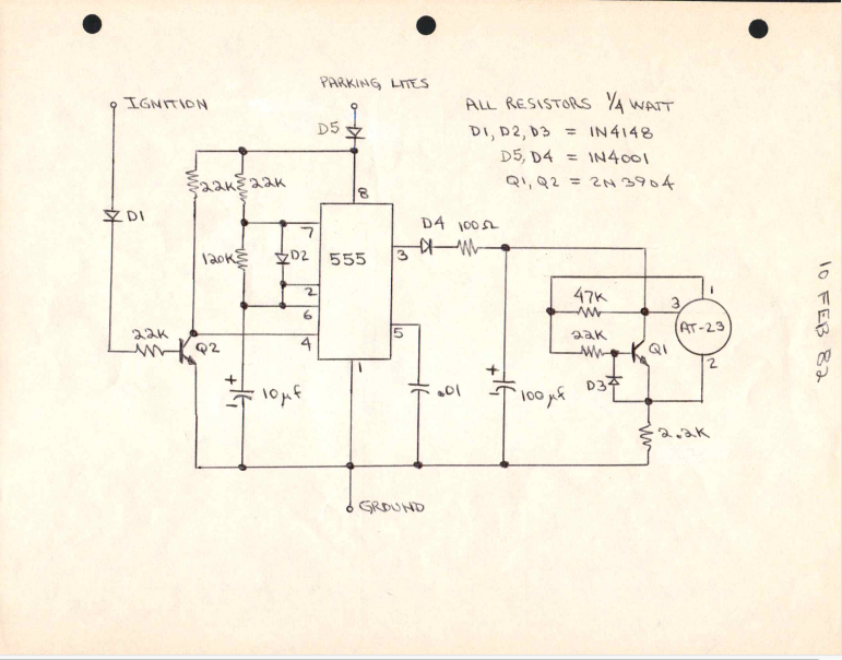
Figure 8 - Bonger Schematic and parts list.
All of the parts for the Bonger (except for the AT-23 and the plastic boxes) were purchased from Digi-Key.
The entire thing is obviously a bit dated but I did indeed use one of these things as part of a later design for the Library where my wife Cindy worked.
OPERATION
Proper installation of the Bonger is a bit tricky. Namely you need to use the three provided scotch locks to attach the three wires on the Bonger to the correct wires under the dashboard of your car. This wasn’t too difficult on an older car (circa 1965) but as the cars got newer the wiring got more and more difficult to access. Not to mention that your newer car probably already had a factory installed Bonger.
So, with all that said, you needed to attach the black wire of the Bonger to a ground, not so difficult. The other two were a bit more challenging. Next, you needed to find a wire that goes from zero to +12 Volta when ever the car ignition was turned on. This usually meant whenever the ignition key was turned to the 1st notch, the accessory position. You connect the green wire to this one. Lastly, you need to find a wire that goes from zero to +12 volts when the parking lights (or the main headlights) are on. You attach the yellow wire to this one.
After you’ve done all of this, you can go ahead and peel off the protective paper from the sticky foam on the bottom of the Bonger and stick it someplace convenient under the dash. Now you’re all set. Installation is completed and you will be reminded that you’ve left your headlights on by a pleasant bell-like sound.
